Conversion of a standard Bell filament Cycle Light to dual LEDs and Lithium batteries
![]() 1 Jan 12 - New page added
1 Jan 12 - New page added
This is a simple design that can use almost any LED provided it is rated for 3.7V or slightly higher. I used a pair of Cree XR-E R2 LEDs, which were the best at the time; however, LEDs are still developing rapidly and there are much more efficient designs now.
| The Bell Cycle Light as supplied and dismantled |

 |
 |
 |
|
| The kit of parts produced for the conversion |
 |
A piece of rigid foam cut to fit around the switches. The material isn't important they are primarily intended to hold the switches in position.
2 Silicone switch buttons (14mm) and 2 push switches as I wanted independent control An Aluminium block that was machined by myself to fit in the back of the clear lens bezel. It features a slight bevel on the front to angle the light beams away from each other a little. 2 Cree XR-E R2 LEDs and 2 moulded lenses for Cree LEDs 2 Lithium 26500 batteries ('C' size) (not shown here) |
||
| The battery terminals are removed from the case |
 |
And modified by cutting off the unnecessary material |
 |
|
| The rear switch slider is removed. The 'oval' switch in this light fits in a recess which is 28mm wide (twice the Silicone button diameter) |
 |
The square hole is open out to be a through hole at the full width of the recess |
 |
|
| This shows the switches and Silicone buttons and modified (left and right of left image). The solder terminals are trimmed and the flange on the switches trimmed on one side flush with the button. Due to the limited space available some of the internal pip needs to be removed by turning the button inside out as shown in the right image |

 |
The switches are slotted into the foam to check the fit The buttons should sit together like this once trimmed |
 |
|
| The battery terminals are reinstalled |
 |
The Silicone buttons are inserted from inside and the switches then pushed to the gap one at a time. A piece a plastic or card can help keeping things in place at this stage |
 |
|
| If there is any gap behind the switches (which allows them to move) a small piece of plastic or card can be inserted behind them |
 |
A small slot is cut in the lamp body between the switches to allow the cables to run through |
 |
|
| Optics with Cree stars in place. A small piece of card was bent and slipped between the optics to keep them pushed outwards, which is removed once bonded |
 |
The LEDs need a good thermal path to the Aluminium block, so it was glued with thermal epoxy and clamped in place until set |
 |
|
| The lamp cluster once bonded, the optics are just a push fit on the LED so can be removed easily |
 |
 |
Wires soldered to stars. The negative lead of one LED and positive lead of the other need to be long enough to reach the switches |
 |
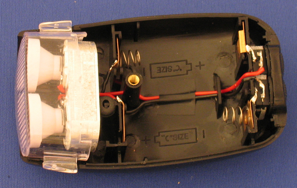
| LEDs fitted and wired up. As I wanted the 2 LEDs to be separate they would each have their own battery. For simplicity the positive of a LED and negative of the other were connected to the nearest battery terminals. The second lead of each was run back the a switch, which was connected to the other battery terminal |
 |
It turns out the 26500 batteries are slightly larger diameter than standard 'C' cells. Material was removed to ensure the batteries fit properly as shown |
 |
|
| The batteries are installed |
 |
WARNING: These Lithium cells can not be charged using a standard (Nickel Cadmium or Nickel Metal Hydride) charger, a special Lithium cell charger is required. |
||
| The completed light |

 |
 |
||
| Beam shots* of the original lamp (left), and modified lamp with 1 LED (middle) and both LEDs (right) being shone on a wall 5m away. Note the beam width increase with 2 LEDs |
 |
 |
 |
|
| Beam shots* of themodified lamp with 1 LED (left) and both LEDs (right) being shone on a sign
in the woods approx. 10m away *All taken at the same settings 4s exposure at f8, ISO200 |
 |
 |
There wasn't any point including an image for the original lamp at this distance, it was effectively totally black | |
This design only works as this type of Lithium battery will not maintain a voltage above 3.7V for any length of time when 1A is being drawn; these Cree LEDs have a nominal specification of 1A at 3.7V although there is a tolerance. If the voltage is above 3.7V for too long the LEDs will burn out as the current drawn is proportional to voltage (and very non-linear).. It would be possible to use the 2-cells in series, a different battery type or a pre-made pack but LED drivers would be need to limit the current to the LEDs. LED drivers can also give the advantage of different power levels to increase runtime or provide flash modes.
There are a lot of different LED drivers for different voltages and with different modes. Examples are:
| During testing the lamp got extremely hot quite quickly when running on both LEDs (not too surprised). I therefore made a heatsink that is screwed to the Aluminium block from the underside |
 |
I also discovered that the original bracket wasn't strong enough for the increased weight of the modified lamp. Fortunately as the original bracket is simply bolted on I replaced it with a more robust design |